Advanced scenario
Robot
With INTERACT you can scenarize robot actuator parts too. It allows you to move robot links or parts to specified keypoints like an assembly step. It can be useful for layout design and collision checking for example.

- First create a [Scenario]
-
Select a part, in the hierarchy, you want to use in your scenario and in the INTERACT menu go to:
INTERACT > Scenarize > Create Actuator.
This will create an Actuator_YourPartName game object in the hierarchy.
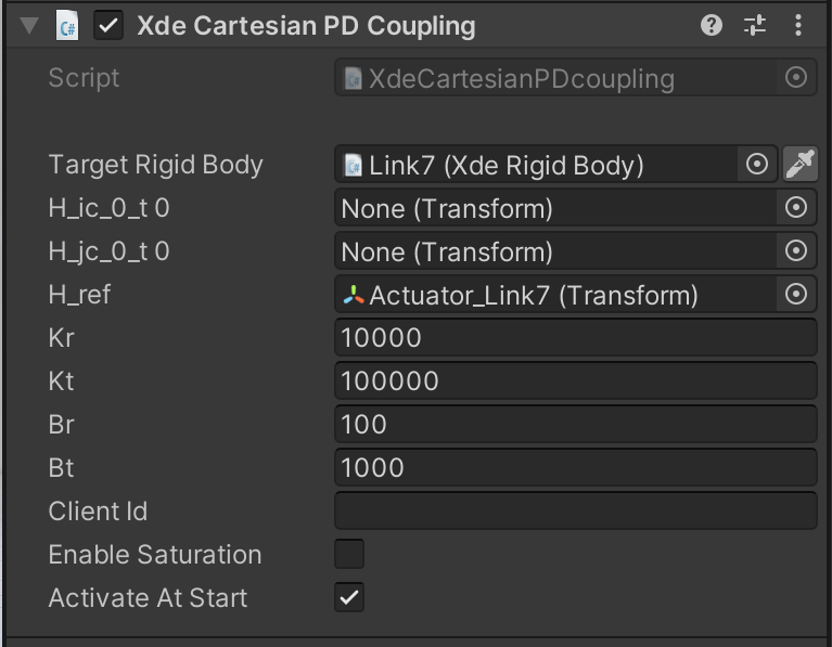
A component named Xde Cartesian PD Coupling is attached to the actuator part. -
Indicate the target of this actuator object: click on INTERACT > Scenarize > Create Actuator Target.
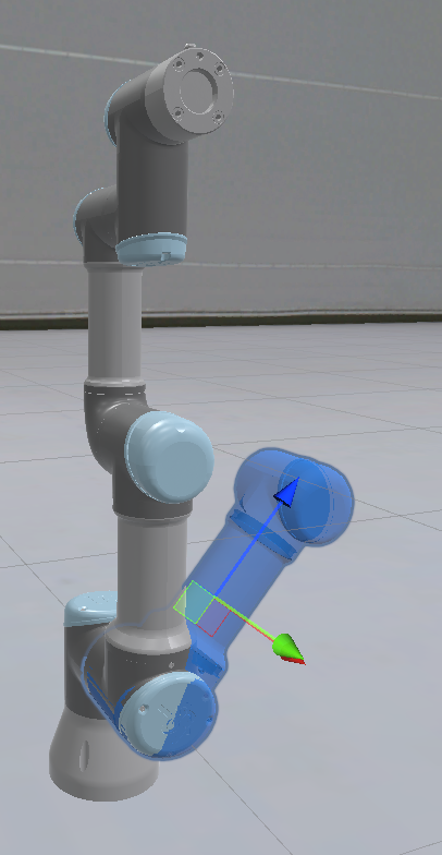
The Target_Actuator_YourPartName (with a Xde Asb Robot Keypoint component attached to it) is created, it has the appearance of a blue ghost.
-
Place this target where the part should go.
- This will also have the effect of creating a Step in your scenario corresponding to the robot move of this part to the target.
Xde Cartesian PD Coupling (Actuator Part)
To add an Actuator part, select your robot part and then: INTERACT > Scenarize > Create Actuator Part.
Add a proportional derivative coupling between a XdeRigidBody and a desired position (Transform).
The Cartesian PD Coupling can be seen as a damped spring attached at one end to the coupled rigid body, and controlled at the other end by the desired position and velocity.

- H_ic_0_t0: Offset between the RigidBody and the spring (expressed in world frame). By default H_ic_0_t0 is set to the identity and the spring is attached to the RigidBody position.
- H_jc_0_t0: Offset between the Reference position and the spring (expressed in world frame). By default H_jc_0_t0 is set to the identity and the spring is attached to H_ref .
- H_ref: Desired position for the current time step. This position is expressed with respect to the ground body.
- Kr: Rotation stiffness.
- Kt: Translation stiffness.
- Br: Rotation damping.
- Bt: Translation damping.
Xde Asb Robot Keypoint
To add a Robot Keypoint, select your Actuator Part and select INTERACT > Scenarize > Create Actuator Target. The target is visible in the scene and represented by a blue ghost. You can place it where you want the actuator to move the robot part.
The target keypoint is represented in the task space (global frame) and not in the joint space.
Thus, when using the robot keypoint for serial robots you have to place and rotate the effector keypoint in the world space and not just rotate it in the joint space.

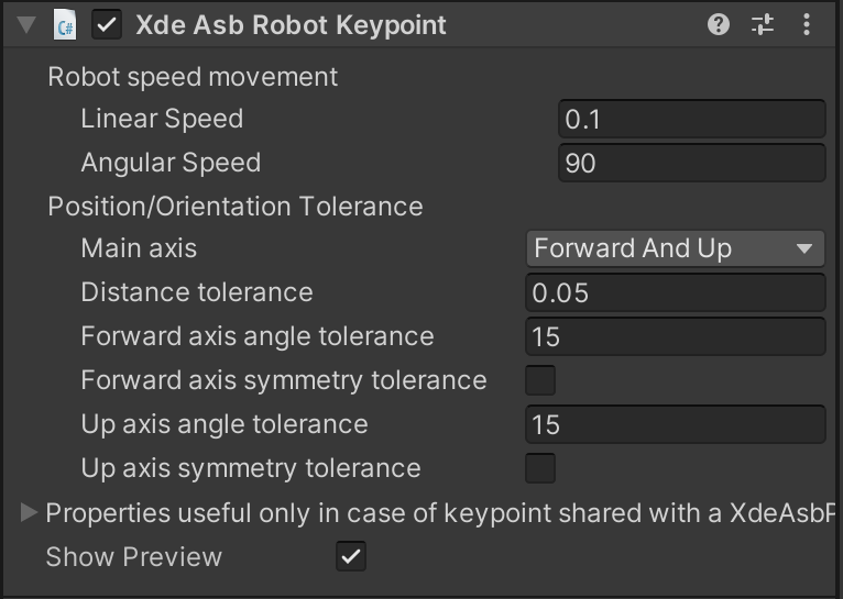
- Linear speed: Movement speed of the robot.
- Angular speed: Rotation speed of the robot.
- Main axis: Two reference axis used to determine the tolerance threshold. [Up and Right], [Forward and Up], [Right and Forward].
- Distance tolerance: Reset distance tolerance (in meters).
- Forward axis angle tolerance: Keypoint axis 1 angle tolerance.
- Forward axis symmetry tolerance: Is the assembly object perfectly symmetric on its first axis.
- Up axis angle tolerance: Keypoint axis 2 angle tolerance.
- Up axis symmetry tolerance: Is the assembly object perfectly symmetric on its second axis.