![]()
Scenarization
An assembly sequence is the order in which different parts are put together to form a complete product. This typically involves a series of steps, in which each part is added to the product in a specific order. Assembly sequences can be created using INTERACT software, which allows to visualize the different parts and how they fit together. The assembly sequence is a critical part of the manufacturing process, as it ensures that the product is assembled correctly and efficiently. Assembly sequences can be part of a training application.
Within INTERACT, you can create assembly sequences using the Scenario Graph.
Create a Scenario
Here are the key steps to create a Scenario in your Unity Editor with INTERACT :
-
Create a scenario, in the INTERACT menu: INTERACT > Scenarize > Create scenario.
This creates a [Scenario] game object in the hierarchy window. -
To make the object accessible from your scenario we need to add a XdeAsbPart component.If it is physicalized it already has one, otherwise, in the hierarchy, right click on your object and go to: INTERACT > Scenarize > Make part grabbable. This will also make it grabbable in VR.
-
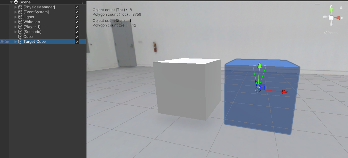
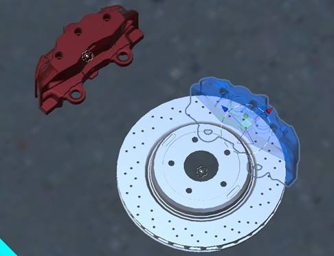
Indicate the target of this object: click on INTERACT > Scenarize > Create Part Target. The target is created, it has the appearance of a blue ghost.

-
Place this target where the part should go.

-
This creates a Placing Step in your [Scenario] with the corresponding part to place and target.

-
To have an overview of the steps, go to: INTERACT > Scenarize > Show scenario graph.
- You will now be able to connect the steps to make sequences (ex: the assembly of a wheel starts only if the brake disk is in place AND the bolts have been screwed).
- You can also give specific names to your Steps.
- Go to Customize scenario to learn more.

The Scenario manager automatically handles the visual helpers in runtime (trajectories, ghost, instruction panel). In Simulation (when you switch to the PLAY mode), the transition between steps is done when the part to place reaches its target.
Edit the Target
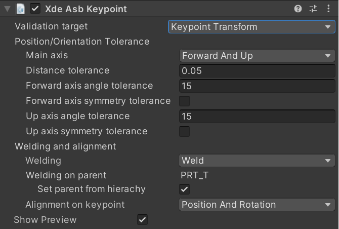
The XdeAsbKeypoint is the component used to set the target of your Placing step. There are two modes for validation target: Keypoint Transform or Joint State.
Keypoint Transform
When using the Keypoint Transform validation target mode, the part to place has to reach the position and rotation of the keypoint.

- Main axis:
You can choose which set of main axis fits the best for your target. These axis are in the local frame of your part :
| Main axis | description |
|---|---|
| Up and Right | Y (green) and X (red) |
| Forward and Up | Z (blue) and Y (green) |
| Right and Forward | X (red) and Z (blue) |
Joint State
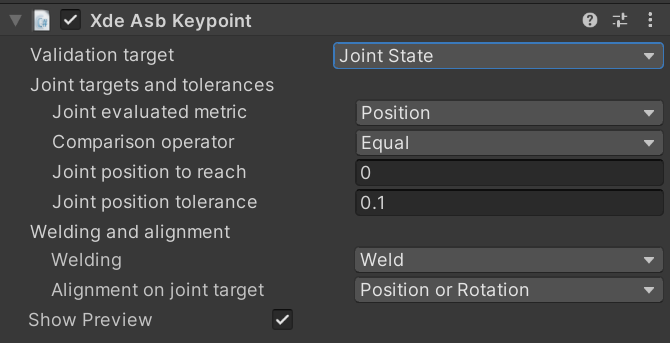
When using Joint State validation target mode, the joint of the part to place (which contains the XdeAsbPart component) has to reach the desired position and/or velocity in joint state.

Xde Unit Joint Monitor
A XdeUnitJointMonitor component is required on the part to place in order to use the Joint State validation target mode.
- Joint evaluated metric: Position, Velocity or Position and Velocity.
- Comparison operator: Choose whether the Joint evaluated metric has to be Equal, Greater than, Less than or not equal to the Joint position/velocity to reach value.
- Joint position/velocity to reach:
float - Joint position/velocity tolerance:
float
Welding and alignment
-
Welding:
Welding description Weld Weld the part to place to the target when keypoint is reached Unweld Unweld the part to place (if already welded to another part) when keypoint is reached None Do nothing -
Set parent from hierarchy is enable the target is weld to the parent GameObject in the hierarchy. If you disable the Set parent from hierarchy property you can choose which rigid body you want to weld your keypoint to.
-
Alignment on keypoint: allows you to set on which keypoint axis the part to place will be aligned to when the validation target is reached :
- Position and Rotation
- Position (see example below)
- Position and Right axis
- Position and Up axis
- Position and Forward axis
- Rotation (see example below)
- Right axis (rotation around X axis)
- Up axis (rotation around Y axis)
- Forward axis (rotation around Z axis)
- None
Examples:
Position: the user only want to align the position of the part to its target and not take into account its rotation:
Rotation: the user only want to align the rotation of the part to its target and not take into account its position (but still in the distance tolerance):
- Show Preview: Show or hide the target preview (blue ghost).